
High Surge Current (D-rated) SIDACtor Device
http://www.littelfuse.com
2 - 10
© 2004 Littelfuse, Inc.
+1 972-580-7777
SIDACtor
Æ
Data Book and Design Guide
High Surge Current (D-rated) SIDACtor Device
DO-214AA SIDACtor solid state protection devices with a D surge rating protect
telecommunications equipment such as modems, line cards, fax machines, and other CPE.
These SIDACtor devices withstand simultaneous surges incurred in GR 1089 lightning
tests. (See "First Level Lightning Surge Test" on page 4-5.) Surge ratings are twice that of a
device with a C surge rating. This allows a discrete surface mount version of Littelfuse's
patented "Y" configuration. (US Patent 4,905,119)
SIDACtor devices are used to enable equipment to meet various regulatory requirements
including GR 1089, ITU K.20, K.21 and K.45, IEC 60950, UL 60950, and TIA-968-A
(formerly known as FCC Part 68).
* For surge ratings, see table below.
** Contact factory for release date.
*** The 2.2 A version cannot be used to meet 4.4 A requirements.
General Notes:
∑ All measurements are made at an ambient temperature of 25 ∞C. I
PP
applies to -40 ∞C through +85 ∞C temperature range.
∑ I
PP
is a repetitive surge rating and is guaranteed for the life of the product.
∑ Listed SIDACtor devices are bi-directional. All electrical parameters and surge ratings apply to forward and reverse polarities.
∑ V
DRM
is measured at I
DRM.
∑ V
S
is measured at 100 V/µs.
∑ Special voltage (V
S
and V
DRM
) and holding current (I
H
) requirements are available upon request.
∑ Off-state capacitance (C
O
) is measured at 1 MHz with a 2 V bias and is a typical value.
Electrical Parameters
Part
Number *
V
DRM
Volts
V
S
Volts
V
T
Volts
I
DRM
µAmps
I
S
mAmps
I
T
Amps ***
I
H
mAmps
C
O
pF
P0080SD **
6
25
4
5
800
2.2
50
200
P0300SD **
25
40
4
5
800
2.2
50
220
P0640SD **
58
77
4
5
800
2.2
50
100
P0720SD **
65
88
4
5
800
2.2
50
100
P0900SD **
75
98
4
5
800
2.2
50
100
P1100SD
90
130
4
5
800
2.2
50
80
P1300SD
120
160
4
5
800
2.2
50
80
P1500SD
140
180
4
5
800
2.2
50
80
P1800SD
170
220
4
5
800
2.2
50
60
P2300SD
190
260
4
5
800
2.2
50
60
P2600SD
220
300
4
5
800
2.2
50
60
P3100SD
275
350
4
5
800
2.2
50
60
P3500SD
320
400
4
5
800
2.2
50
60
Surge Ratings
Series
I
PP
2x10 µs
Amps
I
PP
8x20 µs
Amps
I
PP
10x160 µs
Amps
I
PP
10x560 µs
Amps
I
PP
10x1000 µs
Amps
I
TSM
60 Hz
Amps
di/dt
Amps/µs
D
1000
800
400
300
200
50
1000
High Surge Current (D-rated) SIDACtor Device
© 2004 Littelfuse, Inc.
2 - 11
http://www.littelfuse.com
SIDACtor
Æ
Data Book and Design Guide
+1 972-580-7777
D
a
ta
S
h
e
e
ts
Thermal Considerations
Package
Symbol
Parameter
Value
Unit
DO-214AA
T
J
Operating Junction Temperature Range
-40 to +150
∞C
T
S
Storage Temperature Range
-65 to +150
∞C
R
JA
Thermal Resistance: Junction to Ambient
90
∞C/W
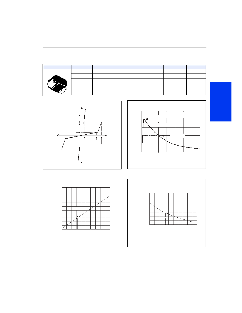
I
H
I
T
I
S
I
DRM
V
DRM
V
T
+V
-V
+I
-I
V
S
I
H
I
T
I
S
I
DRM
V
DRM
V
T
+V
-V
+I
-I
V
S
V-I Characteristics
50
100
0
t
r
t
d
0
Peak
Value
Half Value
t ≠ Time (µs)
I
PP
≠ P
e
ak Pulse Current ≠ %I
PP
t
r
= rise time to peak value
t
d
= decay time to half value
Waveform = t
r
x t
d
t
r
x t
d
Pulse Wave-form
-8
-40 -20
0
20
40 60
80 100 120 140 160
-6
-4
0
2
4
6
8
10
12
14
Junction Temperature (T
J
) ≠ ∞C
P
ercent of
V
S
Change ≠ %
25 ∞C
Normalized V
S
Change versus Junction Temperature
0.4
-40 -20
0
20 40 60 80 100 120 140 160
0.6
0.8
1.0
1.2
1.4
1.6
1.8
2.0
Case Temperature (T
C
) ≠ ∞C
Ratio of
I
H
I
H
(T
C
= 25 ∞C)
25 ∞C
Normalized DC Holding Current versus Case Temperature